Blocking and Non-Blocking Assignment
Let us model a simple design that is given in Figure 1 in Verilog. There are many ways to optimally model the design but here we will learn the difference between blocking and non-blocking assignments in Verilog.
Boolean Equation
We will model our design based on the equations given below.
x = a and b
y = x xor c
z = y
Figure 1: Digital Logic
There are two ways to assign values to LHS in Verilog. But why do we require two methods to perform the same task? When it comes to Hardware Descriptive Language (HDL), it is not as same as software programing, where each line is executed sequentially. In HDL, each line of code is translated to a hardware block by executing the code concurrently. Blocking and non-blocking are the two operators used to assign LHS to RHS. The question is: which operator is used in what scenario?
Blocking
Blocking assignment operator is an equal sign ‘=’. The name blocking derived from its behavior of operation. When a blocking operator is used, the next line of code is blocked until the RHS is evaluated and assigned to LHS.
always@(posedge clk)
        begin
            if(rst) begin
                xb = 0;
                yb = 0;
                zb = 0;
            end else begin
                xb = a | b;
                yb = xb ^ c;
                zb = yb;
            end
        end
In the above example, a OR b is immediately assigned to xb. The expression for yb is not evaluated until xb is updated. Expression for yb is blocked until xb is updated, hence, the name blocking. Similarly, zb is blocked until yb is updated. All the three statements are executed in the same clock cycle one after the other.
Non-Blocking
Non-blocking assignment operator is a less than equal to sign ‘<=’. When a non-blocking operator is used, the LHS is not updated until it executes all the statements in the always block.
always@(posedge clk)
        begin
            if(rst) begin
                x <= 0;
                y <= 0;
                z <= 0;
            end else begin
                x <= a | b;
                y <= x ^ c;
                z <= y;
            end
        end
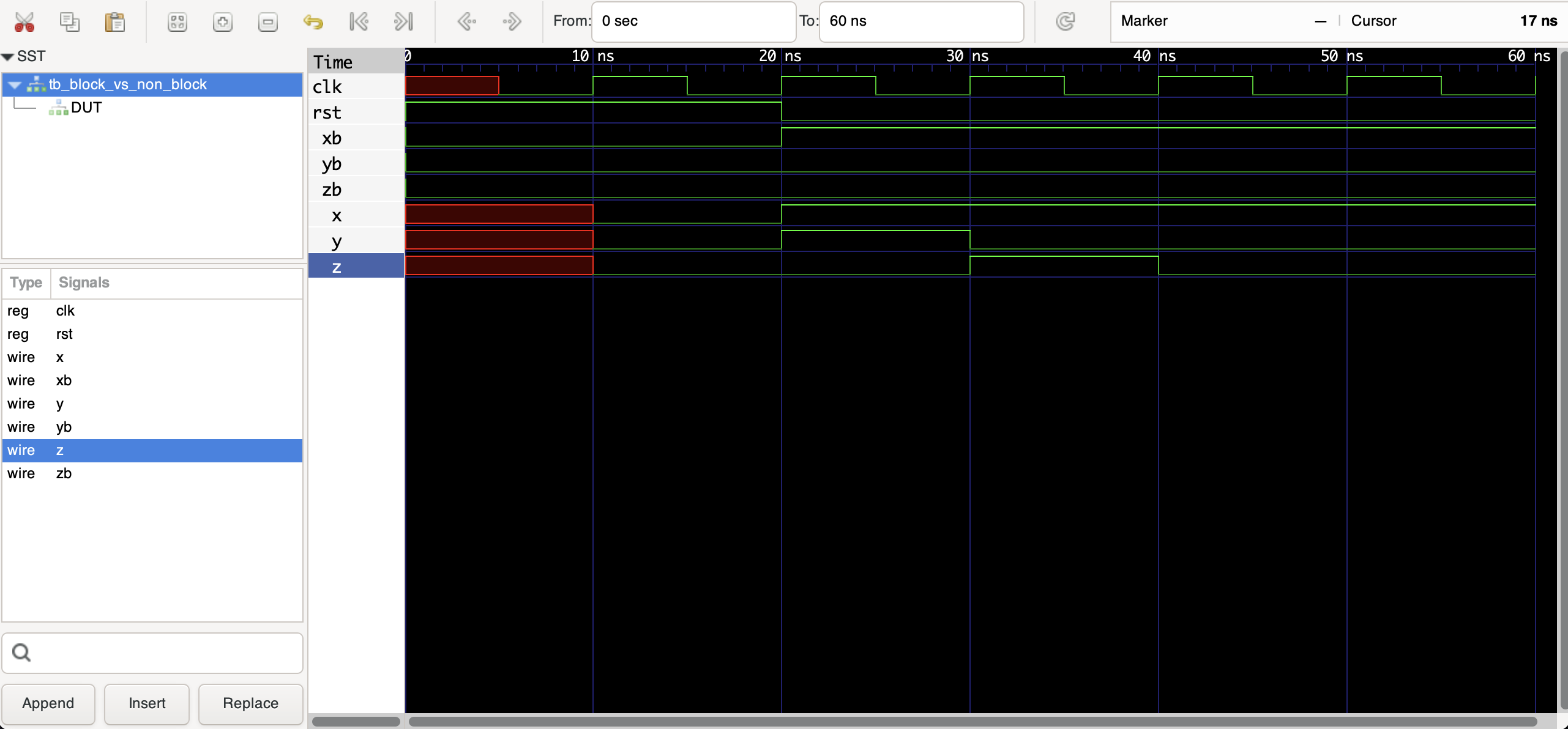
In the above example, LHS is not updated until it evaluates all the RHS expressions. Therefore, it takes 3 clock cycles for z to be updated with the correct results.

Figure 2: Simulated Waveform
From Figure 2, xb, yb, zb are blocking outputs and x, y, z are non-blocking outputs. We are going to concentrate from 20ns to 80ns to understand the concept. Input a, b, c change at 20ns simultaneously, all the blocking outputs are evaluated and updated immediately. Whereas, the non-blocking outputs require three clock cycles to produce the correct output. At 20ns, expression for x evaluates a and b with current inputs; expression for y evaluates with current input of c and previous output of x because x is not yet updated with the new value. Similarly, z is evaluated with previous value of y.
Points to Remember
- When modeling purely combinational circuits, it is generally recommended to use blocking assignments.
- While modeling sequential circuits, non-blocking assignments are preferred.