Adder-Subtractor: An Overview
An adder-subtractor is a combinational digital circuit that can perform the operation of an adder and subtractor based on the control signal. It is an essential component in arithmetic logic units (ALUs) in microprocessors and digital signal processors.
Applications of Adder-Subtractor
- CPUs, microcontrollers, and digital signal processors implement adder subtractors for arithmetic operations.
- Computer graphics make use of adder-subtractors blocks for calculating coordinates and pixel values.
Components of Adder-Subtractor
Binary Adder: A simple Full Adder with three inputs, two significant bits and one carry-in bit, and two outputs sum and carry-out.
2’s Complement: Binary subtraction is performed with the help of 2’s complement. Two’s complement is obtained by inverting the operand and adding 1 to the result. Subtraction is performed by adding the 2’s complement of the subtrahend to the minuend.
Control Signal: The control signal for the adder-subtractor circuit determines whether the circuit performs addition or subtraction. Typically, the carry-in signal of the adder-subtractor circuit is the control signal.
Design: 4-bit Adder-Subtractor
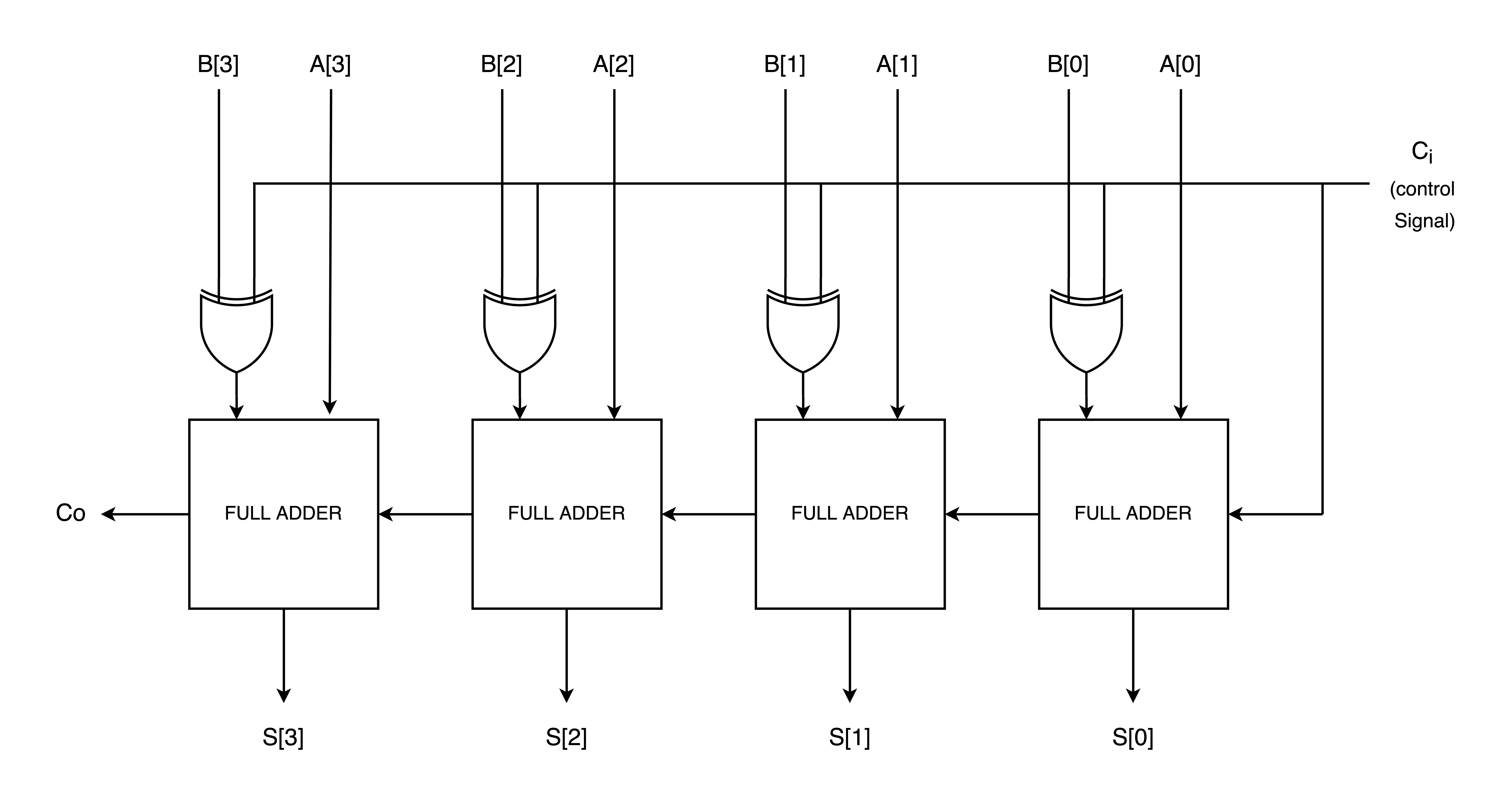
Consider a 4-bit adder subtractor consisting of two 4-bit vectors A and B. The Figure below shows a 4-bit ripple carry adder-subtractor.

Working as an Adder-Subtractor
Addition
- Control signal, Ci, is set low/zero.
- The XOR gate acts as the control switch. When one of the inputs is set to zero it acts as buffer.
- The full adder adds the two inputs to perform simple addition.
Subtraction
- Control signal, Ci, is set high/one.
- The control gate, XOR acts as an inverter when one of its inputs is set to height.
- The inverted input and the non-inverted input are added by the full adder.
- Control signal is also used to perform 2’s complement operation in the full adder to perform subtraction operation.
Verilog Code: Adder-Subtractor
module adder_subtractor #(parameter N = 4)(/*AUTOARG*/
   // Outputs
   sum, co,
   // Inputs
   a, b, ci
   );
   // Outputs
   output [N-1:0] sum;
   output	        co;
   // Inputs
   input [N-1:0] a, b;
   input	       ci;    // control signal

   /*AUTOREG*/
   // Beginning of automatic regs (for this module's undeclared outputs)
   reg			co;
   reg [N-1:0]		sum;
   // End of automatics
   /*AUTOWIRE*/

   logic [N-1:0] b_s;
   logic [N:0]   c;

   always_comb begin
      if(ci)begin
               b_s = ~(b);
      end else begin
               b_s = b;
      end
   end

   always_comb begin
      c[0] = ci;
      for(int i = 0; i < N; i = i+1)begin
               sum[i] = (a[i] ^ b_s[i] ^ c[i]);
               c[i+1] = (a[i] & b_s[i]) | (b_s[i] & c[i]) | (c[i] & a[i]);
      end
      co = c[N];
   end

endmodule