Machine language, which consists solely of 1’s and 0’s, is the language understood by machines. Writing even a simple addition operation in machine language requires extensive effort; therefore, assembly language is used to make programs more readable and understandable for humans. Assembly language is then converted into machine language using a compiler. In this section, basic assembly language operations and the micro-operations required for their execution will be explored.
Load Instruction
The first instruction to learn in RISC-V assembly is how to load an immediate value into a register using the li (Load Immediate) command. This command directly places an immediate (constant) value into a register.
RISC-V has 32 registers, and for this example, we will use a temporary register to store an integer value.
li x5,8
The above instruction loads the value 8 into the temporary register x5. To understand how this command works, let’s look at the figure below, which shows a RISC-V simulation using ripes.me.
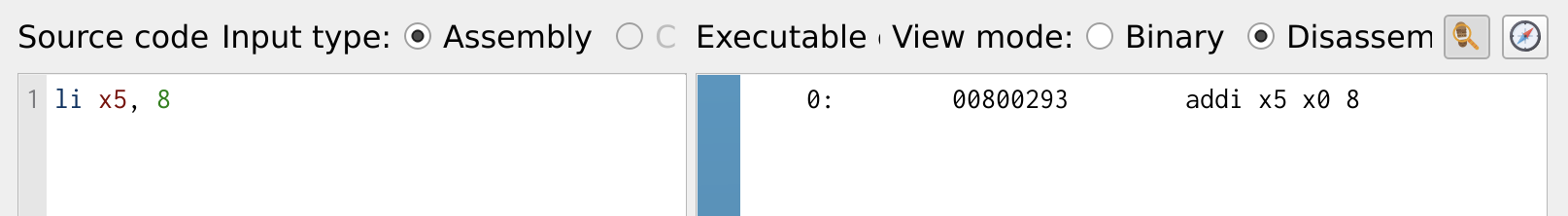
Figure 1: Load Immediate
The li command is a pseudo-instruction in RISC-V, meaning it is not a native hardware instruction but gets translated into actual RISC-V instructions during assembly. Under the hood, li is converted into an addi instruction:
addi x5, x0, 8
Here’s what happens:
- The zero register (x0) always holds the value 0.
- The immediate value (8) is added to x0 and stored in x5.
- This effectively loads 8 into x5.
Another common instruction is lw (Load Word), which loads a value from memory into a register. While li loads an immediate value, lw retrieves data stored in memory.
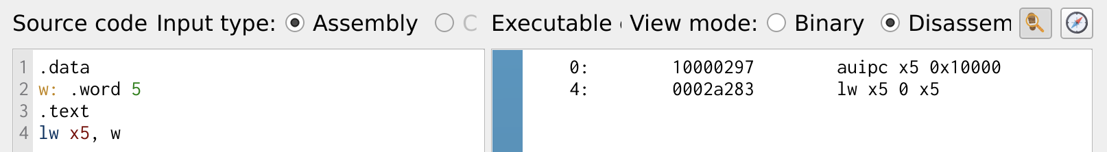
Figure 2: Load From Memory
The .data section is used to store global or static data. The .text section marks the beginning of the program logic that will be executed.
Add and Sub Instruction
Now that we know even a simple load command, which seems trivial, is internally executed using an add instruction, let’s dive deeper into addition and subtraction commands in RISC-V. Let’s explore how the add and sub instructions work and how they manipulate register values in a RISC-V program.
.data
w: .word 5
.text
lw x5, w
li x6, 8
add x5, x5, x6
sub x6, x5, x6
The above program demonstrates loading values into registers and performing basic arithmetic operations using add and sub instructions.
Loading Constants
- The program first loads the constant 5 into register x5. After execution: x5 = 5. Then, the
liinstruction loads the number 8 into register x6. After execution: x6 = 8.
- The program first loads the constant 5 into register x5. After execution: x5 = 5. Then, the
Addition Operation
- The
addinstruction adds the values in x5 and x6 and stores the result in x5. Calculation: x5 = x5 + x6 = 5 + 8 = 13. Now, x5 = 13, while x6 remains 8.
- The
Subtraction Operation
- The
subinstruction subtracts x6 from x5 and stores the result in x6. Calculation: x6 = x5 - x6 = 13 - 8 = 5. Now, x6 = 5, while x5 remains 13.
- The
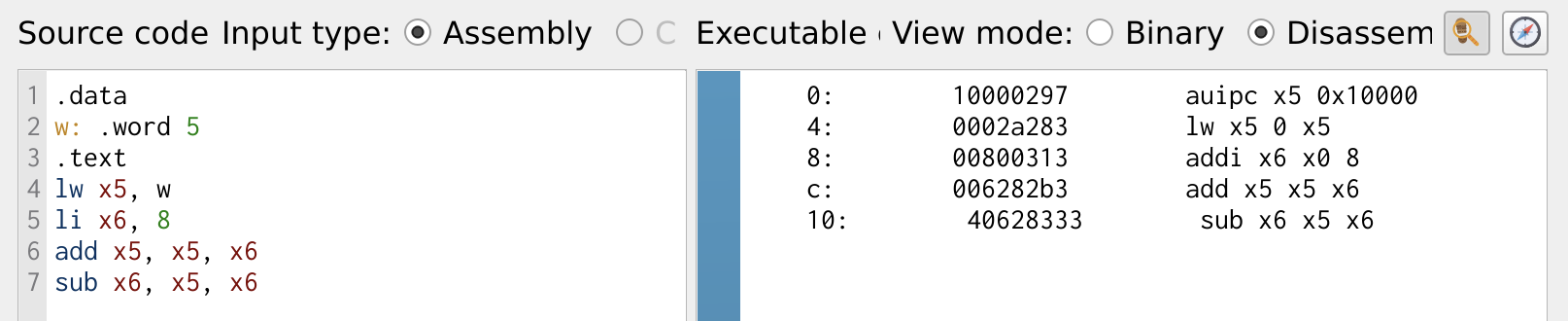
Figure 3: ADD and SUB Instruction
Figure 4, shows the result of data stored in the registers. The register x5 = 13 (0x0d) and the register x6 = 5 (0x05).
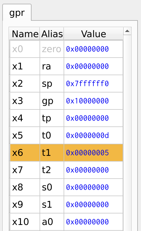
Figure 4: Register Values
Logical Operation
Logical operations in RISC-V include and, or, and xor, which perform bitwise operations on two source registers and store the result in a destination register. In addition to these standard logical operations, RISC-V provides immediate versions of these instructions: and, ori, xori each bitwise logical operation with an immediate value. These immediate versions allow direct manipulation of register values without needing a second source register. Below is a RISC-V program demonstrating the use of logical operations and their immediate versions in action.
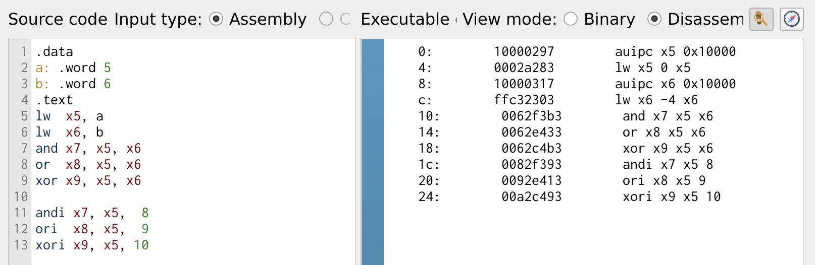
Figure 5: Logical Operations
The register values for the logical operations of the above program is shown in Figure 6.
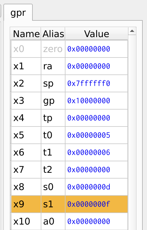
Figure 6: Register Values
The logical operations are simple but the most trivial operations in programming. The and operation is useful for clearing or masking bits, it forces the unwanted bits to zero. The or operation is useful for combining two bits registers, forces a bit to one. The xori operation is used to perform a NOT operation with xori x5, x6, -1. The -1 is 0XFFF is sign-extended to 0xFFFF_FFFF. XOR with all ones will invert the input.
Logical operations are fundamental yet powerful in programming. They allow efficient bitwise manipulation, which is crucial for low-level programming and hardware interactions.
Masking or Clearing Bits
The and operation is primarily used for clearing or masking specific bits. It forces unwanted bits to zero while preserving others.
Combining Bits
The or operation is useful for combining bit values from two registers. It ensures that certain bits are set to one, while leaving others unchanged.
Inverting Bits
The xori instruction is commonly used for bitwise negation, NOT operation). The XOR truth table is shown below:
| A | B | Z |
|---|---|---|
| 0 | 0 | 0 |
| 0 | 1 | 1 |
| 1 | 0 | 1 |
| 1 | 1 | 0 |
The invert operation in assembly is shown below:
xori x5, x6, -1
The number -1 which is 0xF gets sign-extended to 0xFFFF_FFFF, meaning all 32-bits are ones. Performing an XOR operation with all ones effectively inverts the bits of x6, storing the result in x5.
Shift Operation
As the name suggests, the input is shifted to left or right dropping the bits at the end. The left shift adds zeros to the least significant bit. And the right shift can be arithmetic or logical. Just like logical operations the shift operation also have it shift immediate counterparts.
As the name suggests, shift operations move the bits of a register left or right, dropping or preserving the bit. These operations are useful for multiplication, division, and bit manipulation.
- Left shift (
sll): The input shifts the bits to the left, filling the least significant bits with zeros. This operations is smilar to multipling the number by 2ⁿ, where n is the shift amount. - Logical Right Shift (
srl): The right shift the data to the right by the desired amount and fills the most significant bits with zeros. This is and unsigned shift. - Arithemetic Right Shift (
sra): Preserves the sign bit (most significant bit), ensuring correct division for signed numbers.
Right shift also suffices as a 2ⁿ division. Like logical operations, shift instructions also have immediate counterparts slli, srli and srai, where the shift amount is provided as an immediate value instead of a register.
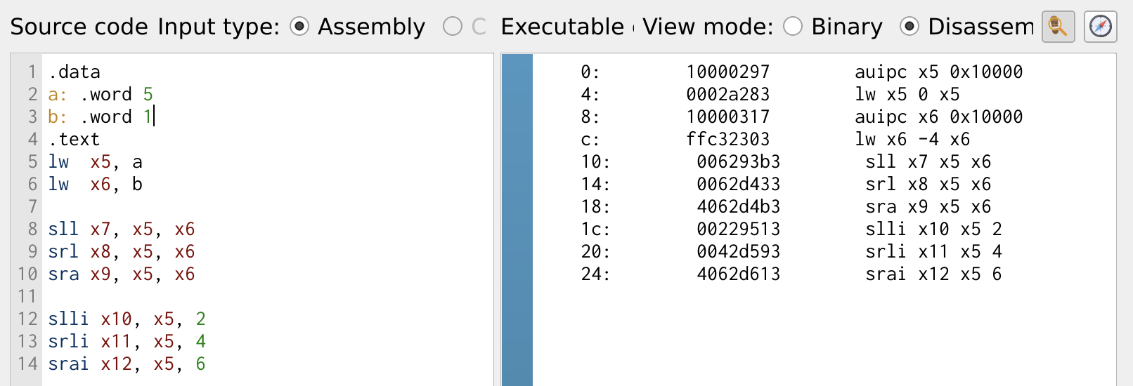
Figure 7: Shift Operation
The register values are shown in Figure 8.
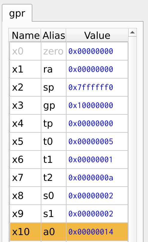
Figure 8: Register Values
Multiply Instruction
Multiplication is one of the fundamental computational operations. When multiplying two N-bit numbers, the result is a 2N-bit product. Since RISC-V is a 32-bit architecture, special handling is needed for 64-bit results.
- 32-bit Multiply (
mul): Multiplies two 32-bit numbers and retains only the least significant 32 bits. The upper 32 bits are discarded. Best used when the product is known to fit within 32 bits. - 64-bit Multiply High: For full 64-bit multiplication, RISC-V provides three variants to store the most significant bits separately:
mulh: Treats both operands as signed.mulhsu: Treats the first operand as signed, second as unsigned.mulhu: Both operands are unsigned.
By combining mulh and mul, a full 64-bit product can be stored across two registers, enabling high-precision arithmetic.
Figure 9 shows the multiplication operation in RISC-V assembly. Two 32-bit values are loaded into registers x5 and x6. The mul instruction multiplies these values and stores the lower 32 bits of the result in register x7. To handle the full 64-bit product, the mulh instruction is used in combination with mul to store the upper 32 bits of the result in x8 and the lower 32 bits in x9. This way, the 64-bit result is is obtained and split across two registers, x8 and x9.
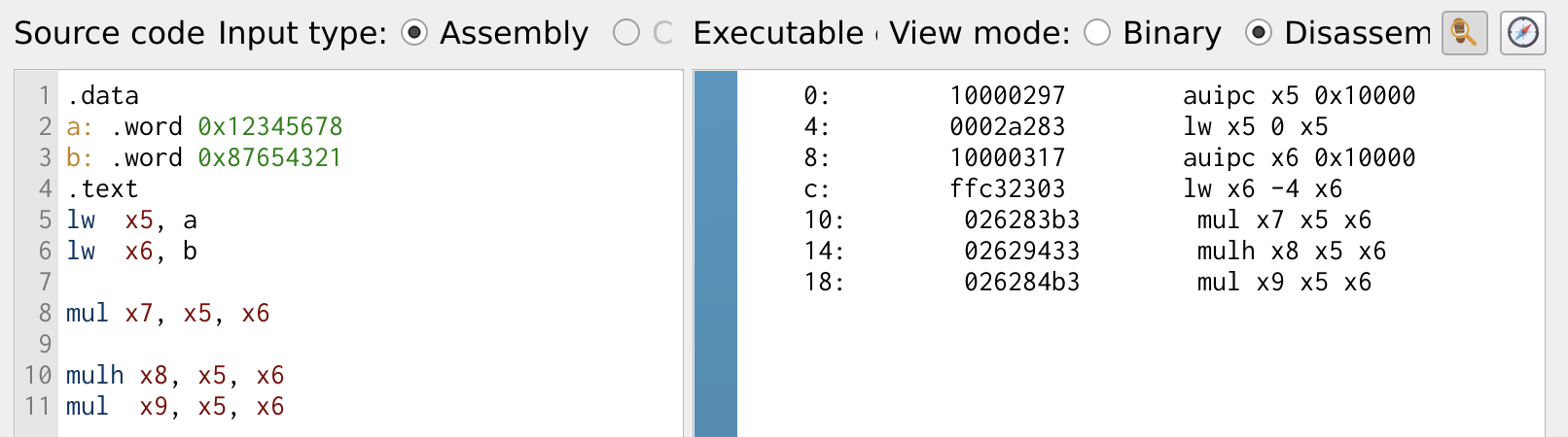
Figure 9: Multiplication Operation
The register values are shown in Figure 10.
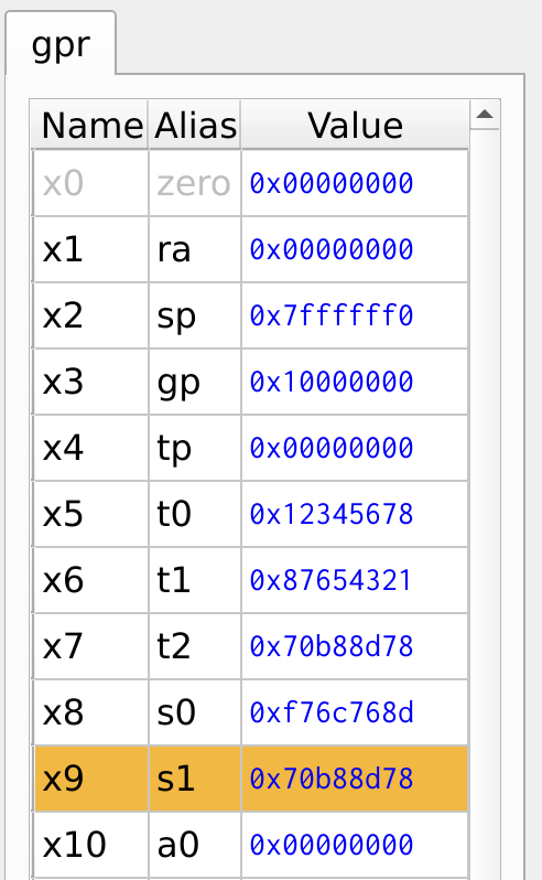
Figure 10: Register Values
Conditional Branches
Branch instructions are used to either execute or skip certain instructions based on the comparison of two values. In RISC-V, there are a total of six branch instructions, which allow for conditional jumps in the program flow. These instructions are as follows:
beq: Branch If Equalbne: Branch If Not Equalblt: Branch If Less Thanbge: Branch If Greater Thanbltu: Branch If Less Than (unsigned)bgeu: Branch If Greater Than (unsigned)
A label is used in conditional branch instructions to specify the target location where the program should jump, depending on whether the condition is satisfied or not. Figure 11, illustrates the use of conditional branching in a program. If a branch condition is satisfied, the program jumps to the target label or else the program flow continues.
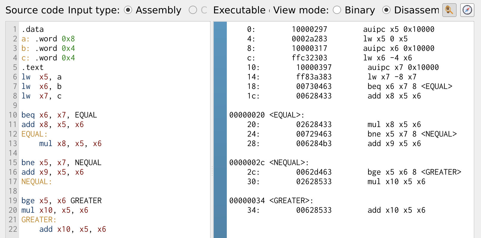
Figure 11: Multiplication Operation
The register values are shown in Figure 12. The register x9 remains zero because the branch condition is satified and the program skips to the specified label.
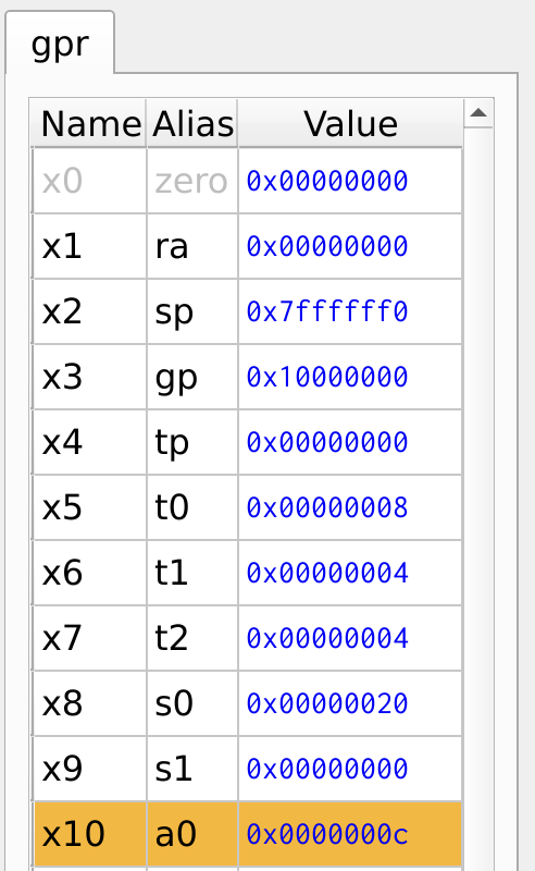
Figure 12: Register Values
Jumps
The jump instruction allows the program to skip a set of instructions and continue execution from a target label. RISC-V provides three types of jump instructions:
- Jump
j– A simple jump that ensures certain lines of code are skipped. - Jump and Link
jal– Used to call a function while saving the return address. - Jump Register
jr– Used to return from a function by jumping to the address stored in a register.
The program below shows the execution of a simple jump instruction.
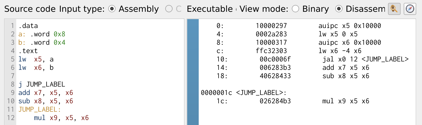
Figure 13: Jump Instruction
By examining the register values, it is evident that registers x7 and x8 remain zero, indicating that the add and sub instructions were skipped.
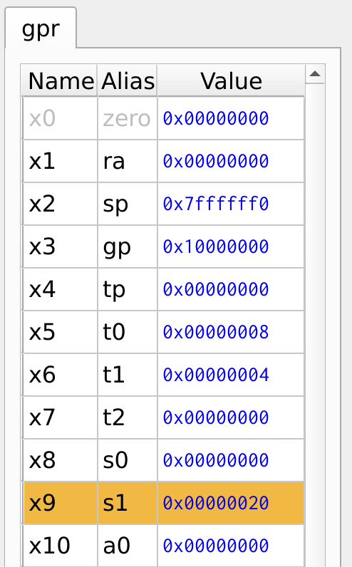
Figure 14: Register Values
If and If/Else Statments
Now that we have learned about conditional branch and jump instructions, let’s implement if and if-else statements—one of the most widely used branching constructs in high-level programming languages.
If Statement
The if statement can be implemented using conditional branch instructions, as demonstrated in the program below:
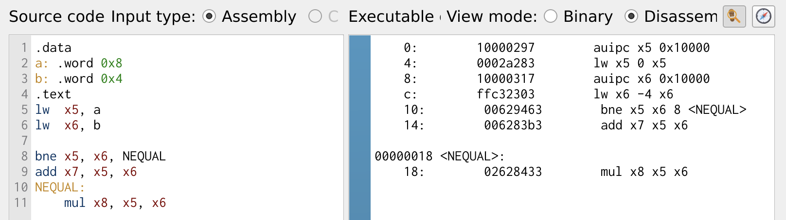
Figure 15: If Statement
In the program, if the values in registers x5 and x6 are not equal, the execution jumps to the branch label NEQUAL. This means the instructions immediately following the condition are skipped, and the program continues execution from the labeled section.
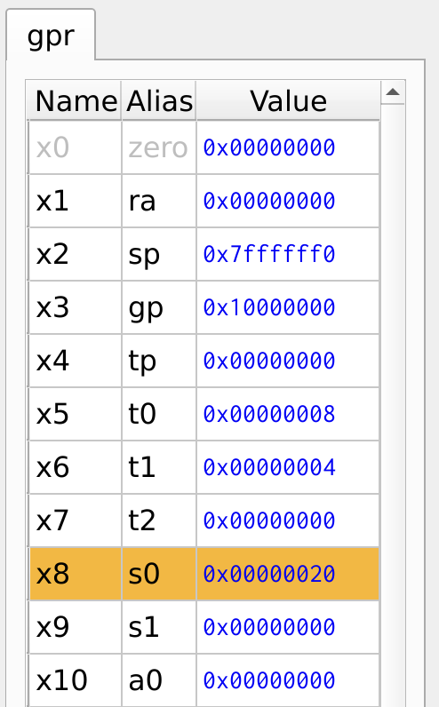
Figure 16: Register Values
If/Else Statement
Similar to the if statement, the if-else statement uses conditional branch along with jump instruction to perform the else operation. The program below illustrates the implementation of if-else statement.
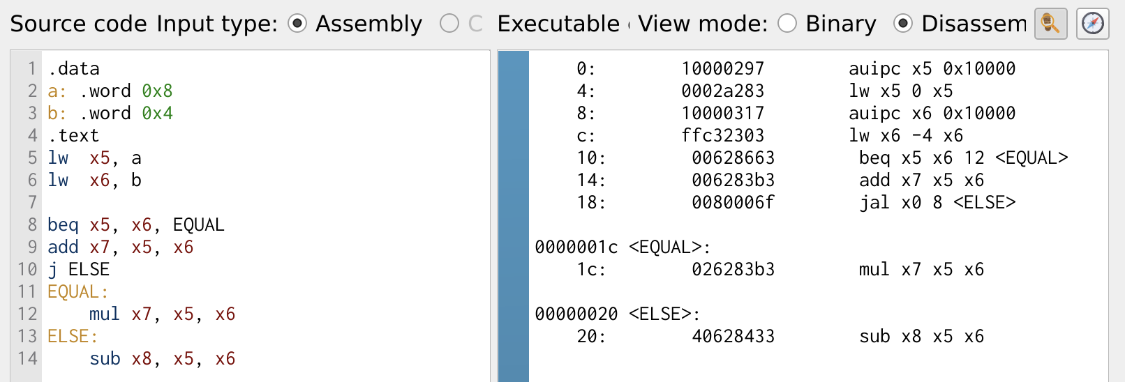
Figure 17: If Statement
In this case, if the values in registers x5 and x6 are equal, the program takes the branch. Otherwise, it continues executing the immediate instructions. The jump instruction j ensures that the branch executes correctly by jumping to the else label, handling the else statement effectively.
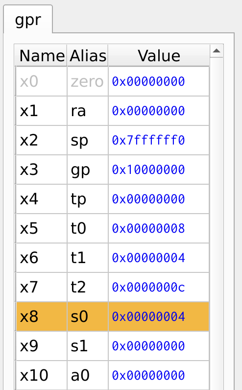
Figure 18: Register Values
Case Statement
A case statement is another form of the if-else condition commonly used in high-level languages to select an output from multiple input conditions. In RISC-V, case statements are implemented using a combination of conditional branch and jump instructions to efficiently execute the corresponding code block based on the given condition.
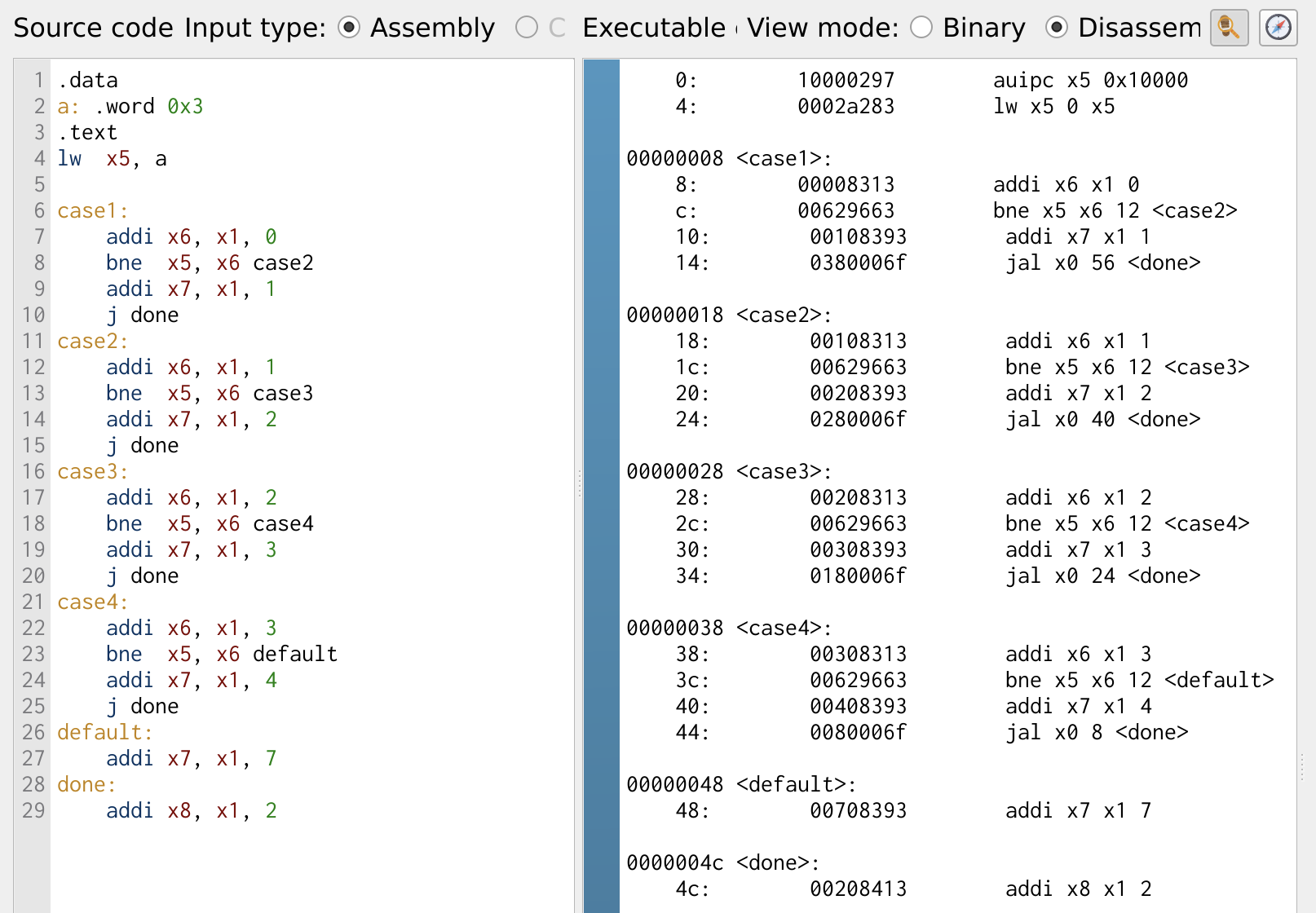
Figure 19: Case Statement
The program demonstrates a simple 2:1 multiplexer (MUX) implementation using conditional branching. Here, the select line is stored in register x5. The case statement checks for values ranging from 0 to 3, and if the select line matches any of these values, the output is set to select line + 1.

Figure 20: Register Values
While Loops
Loops are a crucial programming construct that allows a piece of code to be executed repeatedly. One of the most commonly used looping structure is the while loop. In assembly, loops are implemented using conditional branching in combination with jump instructions. In the following program, we will explore how to implement a while loop in RISC-V using branch and jump instructions.
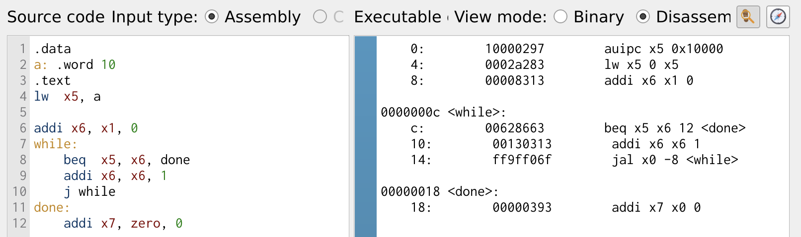
Figure 21: Case Statement
The program demonstrates a simple counter using branch, jump and arithmetic instructions. The counter is stored in register x6, and it increments until it reaches the value stored in register x5. The beq (branch if equal) instruction checks whether the value in x6 is equal to x5. If the values are not equal, the counter x6 is incremented by 1, and the loop continues. Once x6 reaches x5, the program branches to the label done, exiting the loop.
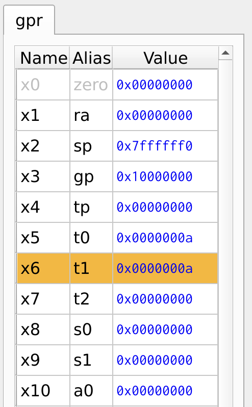
Figure 22: Register Values
For Loop
Another important looping construct is the for loop, which provides a structured way to repeat a block of code with an initialization, condition check, and iteration step. Let’s implement another counter program using a for loop, with a slight variation from the previous example. This version explicitly sets up the loop with an initial value, a condition check, and an increment operation, closely resembling the for loop structure in high-level languages.
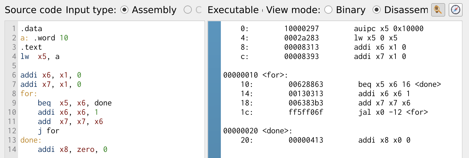
Figure 23: Case Statement
The program computes the sum of a sequence by repeatedly adding the value of i to sum. The sum is stored in register x7, while the loop variable i is stored in register x6. A branching condition checks whether i has reached the total number of iterations stored in register x5. If i is not equal to x5, the loop continues, adding i to sum and incrementing i. Once i reaches x5, the loop exits, and the final sum is stored in x7.
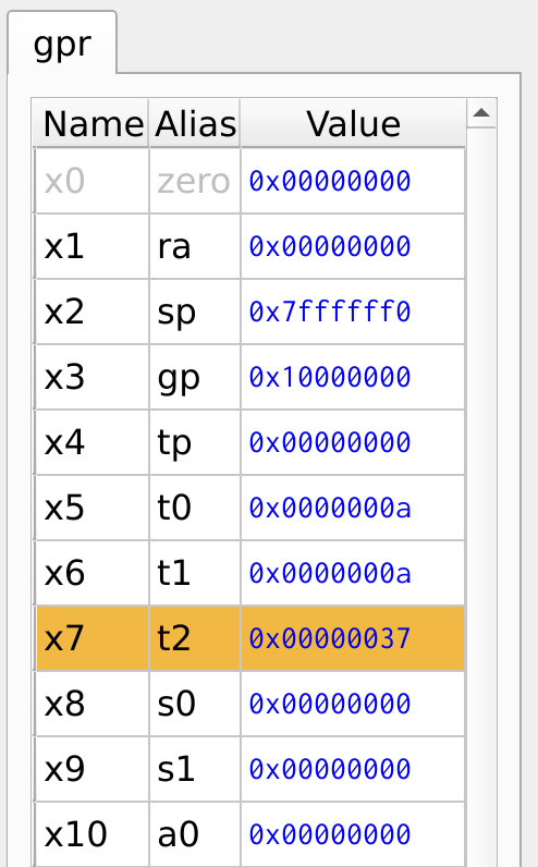
Figure 24: Register Values
Function Calls
Function calls are an essential design methodology that allows code reuse. In RISC-V, function calls are implemented using the jump and link jal instruction and jump register jr instruction, with the return address ra register storing the return location. The following program demonstrates function calls for simple addition and multiplication operations in RISC-V assembly. These functions take two input values, perform the respective operations, and return the result.
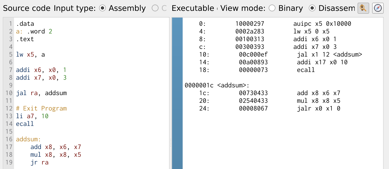
Figure 25: Function Call
In Figure 25, the right side displays the memory address corresponding to each instruction. This helps visualize how instructions are stored and executed sequentially. Figure 26 illustrates the register values after executing the function. Notably, the return address ra register holds the value 14, which corresponds to the next instruction after the function call. This ensures that after executing the function, the program resumes execution from the correct point. This way the jump and link jal, jump register jr, and return address ra register to manage program flow efficiently.
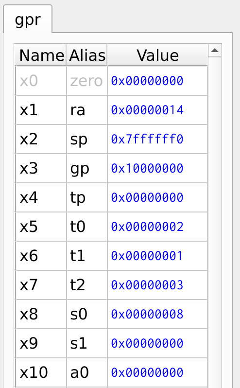
Figure 26: Register Values
Stack
The stack is a crucial memory element in a processor, primarily used for storing register contents when a program exhausts resources or during a function call, where register values need to be saved before modification. The stack pointer sp points to the address of the stack. Unlike regular memory storage, where addresses increase as data is stored, the stack follows a last-in, first-out (LIFO) principle. The stack pointer starts at the highest memory address and decrements as data is pushed onto the stack. This mechanism ensures that temporary data, such as function arguments and return addresses, are efficiently stored and retrieved, making function calls and resource management efficient.
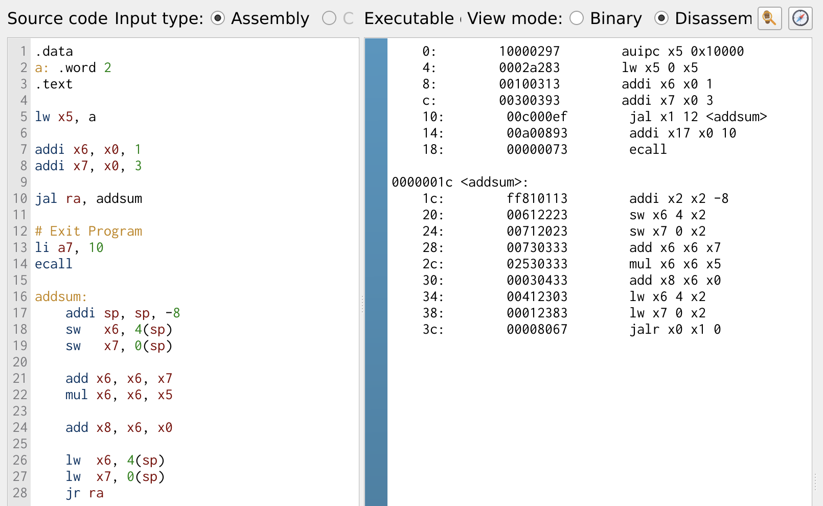
Figure 27: Stack for Storing Register Values
The example program used in fucntion call is modified to save the register contents onto the stack before performing the arithmetic operation. Figure 27 illustrates the use of the save sw and load lw instructions to store and retrieve register values from the stack. Before storing any data, it is essential to allocate the required memory space on the stack. This is done by decrementing the stack pointer sp by 8, ensuring enough space to store two 32-bit values.
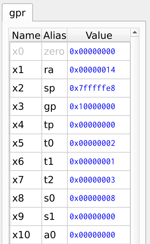
Figure 28: Register Values
Figure 29, shows the contents of the stack memory. The register value x6 and x7 are stored in the addresses 0x7FFF_FFEC and 0x7FFF_FFE8 respectively.
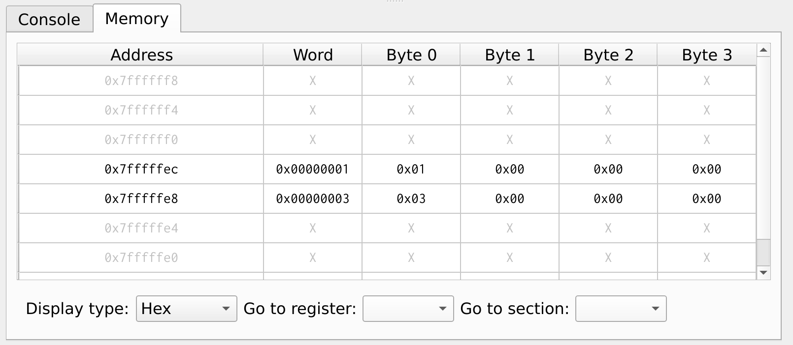
Figure 29: Stack Memory
Recursive Function
One of the classic examples of a recursive function is computing the factorial of a number. Recursion is a powerful concept where a function calls itself to break down a problem into smaller subproblems. Below, we first implement the factorial function in C, followed by its equivalent RISC-V assembly implementation, demonstrating how recursion is handled at the low level.
int fact (int n){
  if(n<=1){
    return 1
} else {
    return (n * fact(n-1))
}
Let’s take an example where n = 4, and the function fact(4) is called. The if condition checks whether n is less than or equal to 1. If true, it returns 1. Otherwise, the else condition is executed, which returns the multiplication of n * fact(n-1).
For n = 4, the function returns:
4 * fact(3)
This process continues recursively until n-1 reaches the base case (n = 1). At this point, the recursive calls begin to resolve, forming the expression:
(4 * (3 * (2 * (1))))
Figure 30 illustrates the assembly implementation of a recursive function. To ensure the recursion works effectively, it is necessary to store the return address ra and any registers that will be modified on the stack before making repeated function calls. In this example, the register x5 is saved on the stack along with ra before each recursive call. This preserves the previous values, allowing the function to return correctly once the recursion starts unfolding.
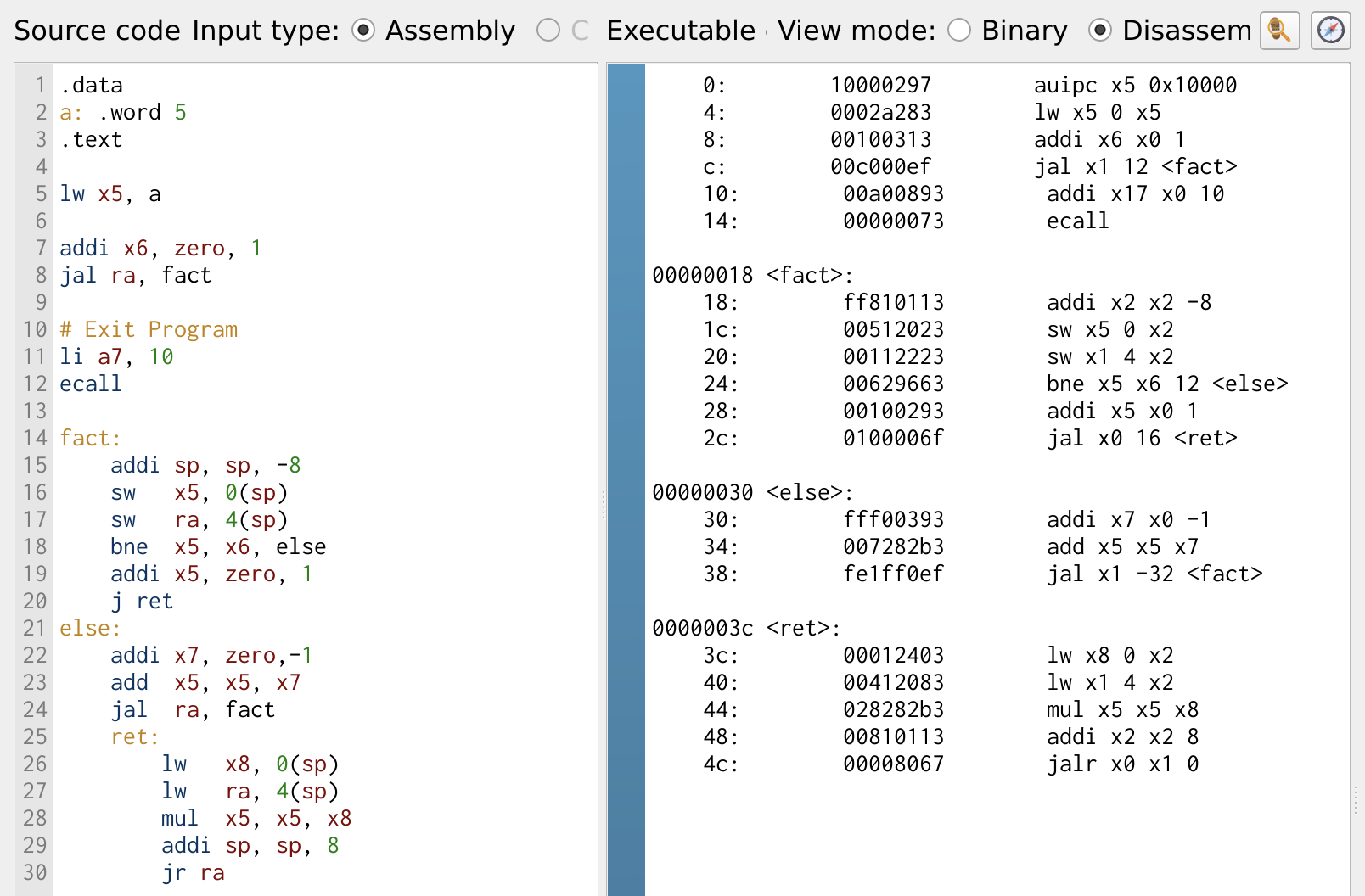
Figure 30: Factorial Program
Figure 31, shows the register values of the program, the register x5 hold the result of the factorial.
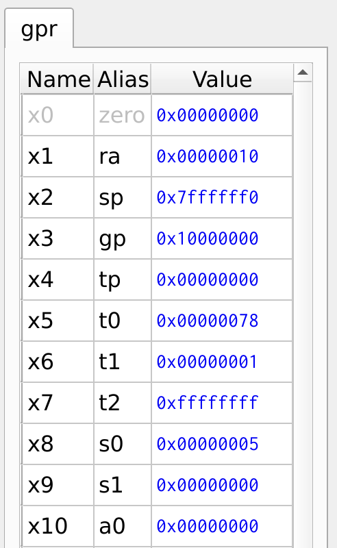
Figure 31: Register Values
Figure 32 illustrates the stack memory layout during a recursive function call. The memory address 0x7FFF_FFEC holds the return address ra register, while 0x7FFF_FFE8 stores the value of register x5. Each time a function call occurs, the current return address and register values are pushed onto the stack, ensuring they can be restored once the function completes and returns.
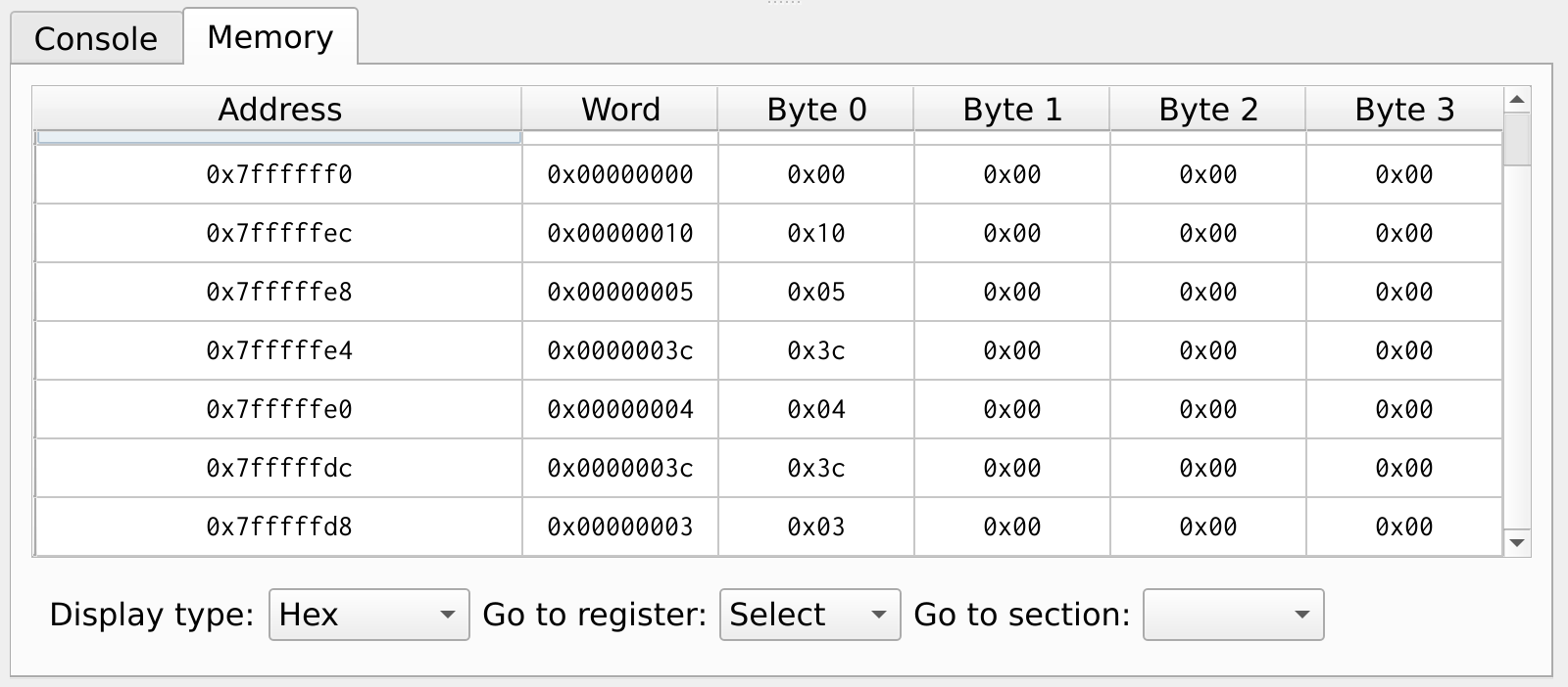
Figure 32: Stack Memory