My doctroal research concentrates on designing a wideband digital receiver system to receive and process the data for accurate multiple signal detection. Fast Fourier transform (FFT) is a widely used digital signal processing technique to detect signals in a bandwidth. However, there are some limitations when using the FFT algorithm for signal detection
- The number of fixed-length samples used by the FFT algorithm determines the frequency resolution. The number of samples from the input signal must be increased to increase the frequency resolution.
- Increasing the number of samples for FFT calculations may increase the frequency resolution but increases the complexity of the algorithm.
- Signal detection becomes much more difficult in the presence of noise and interference.
- Since the FFT algorithm assumes that the fixed-length samples are periodic, in reality, the starting and ending position of fixed lengths of data is not the same, making the signal non-periodic, which leads to spectral leakage and false signal detection in the presence of noise.
- Limited hardware resource that provides maximum accuracy for signal detection poses a significant design challenge to the engineer.
The research provides a hardware efficient algorithm to implement the FFT technique for accurate signal detection
Hardware Setup
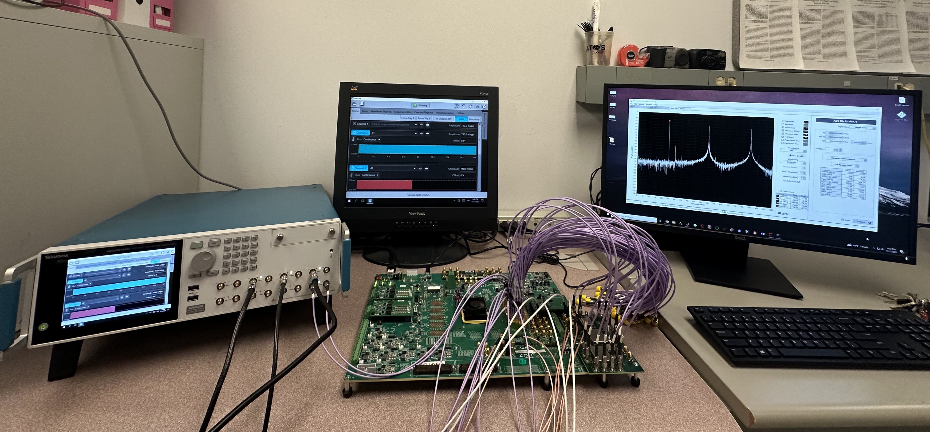
The overall hardware setup for FFT analysis is shown in figure below. The hardware setup begins with a signal source, Tektronix 5200, with the addition of White Gaussian noise. The signal generator is source for the input signal and clock frequency for the analog-to-digital (ADC) present on Zynq UltraScale+ RFSoC 1275. The RF Power combiner is utilized to combine two or more signals for multiple signal detection.

Figure 1: Hardware Setup
Design Flow
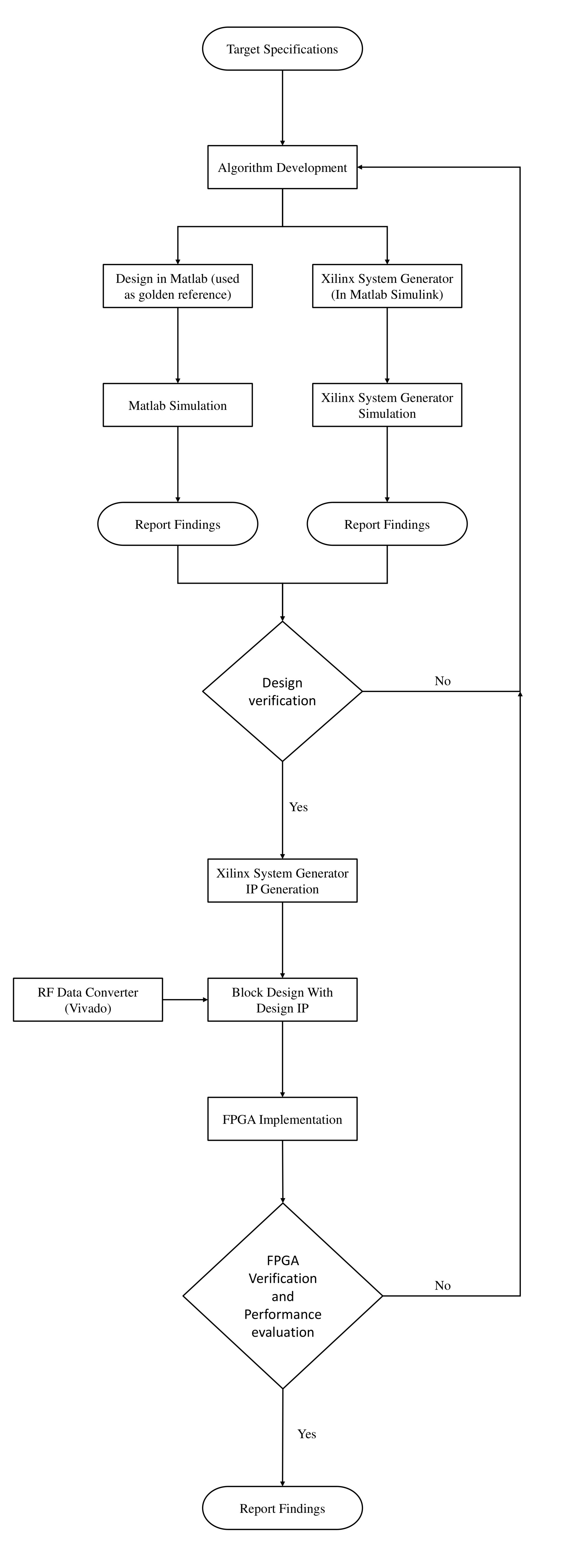
Matlab and Xilinx Model Composer tool sets are employed to design, simulate and verify the functionality of the proposed digital receiver. The top-down approach for the implementation is shown in the flowchat which illustrates a general design approach undertaken to design the wideband receiver. Matlab results are used as a golden reference to verify the proposed FFT hardware. The digital wideband receiver is designed and simulated using Model Composer (Previously known as System Generator).

Figure 2: Design Flow
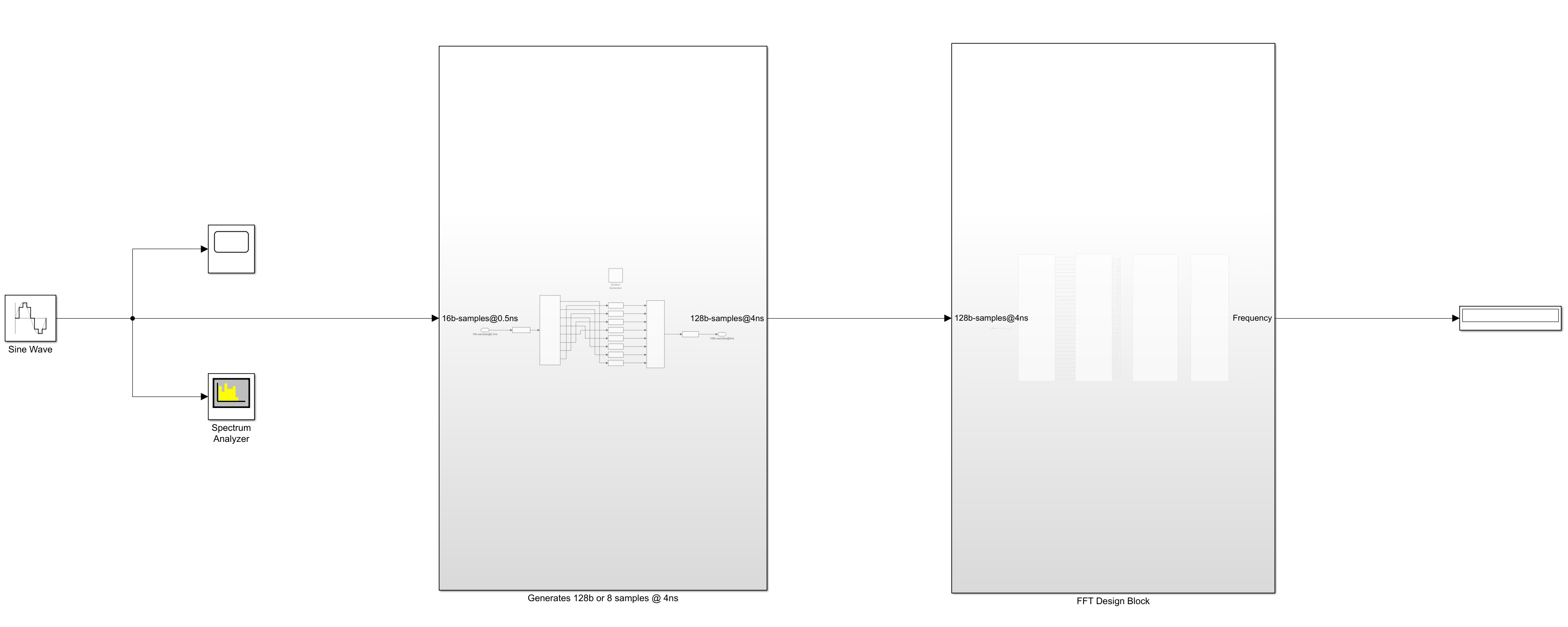
FFT Core Designed and Tested in Xilinx Model Composer
Figure shows the design of the FFT processor in Model Composer used for simulation.

Figure 3: FFT IP Core Testing in Model Composer
Implementing the FFT algorithm in hardware comes with its own set of challenges due to the complexity of the algorithm and the requirements of real-time processing. Here are some of the key challenges involved in FFT hardware implementation and hardware optimization to overcome:
Algorithm complexity: Multiplication operations were replaced by shift and add method to reduce complexity, increase speed, and introduce parallelism.
Fixed-point arithmetic: Dynamic Kernel function algorithm is an extension for fixed-point kernel where the unit circle is expanded by higher powers of two.
Numerical precision and accuracy: The FFT algorithm involves repeated numerical operations, which increases the word length at every stage, [Multiple Input Selection (MIS)] scheme is implemented to maintain precision accuracy while quantizing the output to a specific length at each stage.
Magnitude and peak detector: Both the magnitude estimator and peak detector are valuable tools for understanding the spectral content of a signal. Chebyshev coefficients and an advanced peak detector algorithm are implemented for accurate signal detection.
Parallelism and pipelining: The FFT algorithm naturally lends itself to parallel processing, essential for achieving high throughput in hardware implementations. Designing an efficient parallel architecture and managing the data flow through different processing stages is feasible with Xilinx Model Composer.
Dual Channel FFT Processor
Figure 4: Proposed Method
- Multiplication complexity is reduced with the implementation of shift-and-add operation in the butterfly block.
- Multiple Input Selection (MIS) is a technique used to scale weak signals appropriately and maintain constant word length when data flows through the FFT stages.
- [Chebyshev coefficient for square root approximation] for calculating the magnitude of the FFT output.
- Single channel FFT shows significant improvements resulting with the lowest detectable signal strength is 500 uVpp. Single signal dynamic range (DR) is about 51 dB and maximum two-tone instantaneous dynamic range (IDR) is around 37 dB.
- A frame-based dual-channel FFT approach desogend for the detection of three signals with a minimum separation of three frequency bin (11.72 MHz).
- [Enchanced signal detection] algorithm for multiple signal detection.
The proposed method incorporates a frequency detection scheme comprising three peak detection blocks, including intermittent harmonic filtering blocks. This configuration ensures the capability to detect both strong and weak signals, relying solely on the primary channel, as long as the distance between the closest peaks is a minimum of four frequency bins (15.625 MHz). To enhance signal detection robustness, we utilize differences between peaks identified in primary and auxiliary channels. This strategy reduces false alarms without a predefined threshold, enabling peak identification with a minimum separation of three frequency bins (11.72 MHz) and a minimum signal strength of 40mVpp. The implemented design achieves exceptional performance, maintaining accurate detection rate for three signals across eight distinct test scenarios with varying strengths. This highlights the effectiveness of the approach in reliably detecting signals with diverse magnitudes and frequency separations.
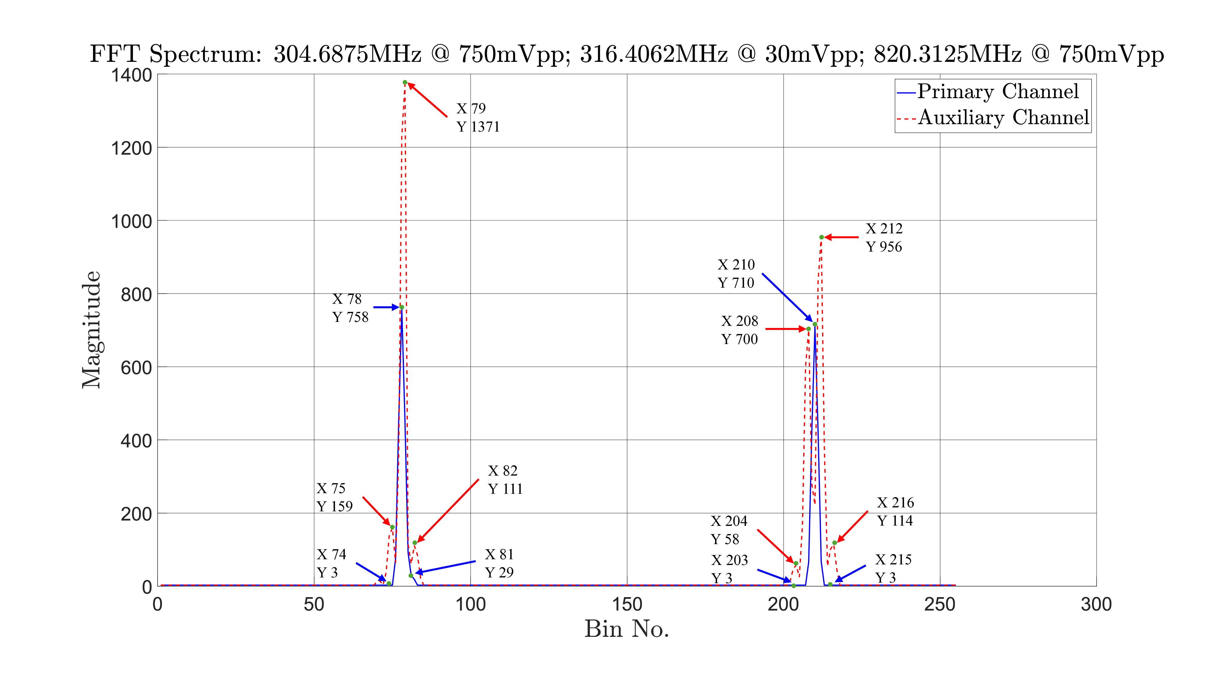
The proposed method can detect two signals at least three frequency bins apart. Two strong signals and two weak signals can be detected with less complication. The complication arises when a weak signal is located close to a strong one. The proposed method utilizes the primary and auxiliary channel output to make a decision in selecting the correct frequency location. The frequency bin location is utilized to calculate the frequency. Figure 5, shows the magnitude spectrum of three signals where the two strong signals are placed far apart and the weak signal is placed close to strong one. Applying the enchanded signal detection algorithm, the detected signals are at located bin location 78, 81 and 210. The two extreme peaks that are place far apart are at bin location 78 and 210 are detected by the primary channel. To detect the third signal, the FFT magnitude spectrum from the auxiliary channel is analyzed and used by the enchanded signal detection algorithm to detected the third signal at bin location 81.

Figure 5: Dual Channel FFT Spectrum

Figure 6: Hardware Setup
Publications
- “Enhancing Two-Signal Instantaneous Dynamic Range: A High-Performance FFT-Based Digital Wideband Receiver with Xilinx UltraScale+ RFSoC for Detecting Multiple CLosely Spaced Signals with Minimal Prior Knowledge.” (Under Review: IEEE Transactions on Aerospace and Electronic Systems)
- “Dual-Channel Multi-Frame FFT Processing for Precise Multi-Signal Detection in Closed-Space RF Environments.” IEEE Transactions on Instrumentation and Measurement (2025).
- “Enhanced Wideband Frequency Estimation via FFT: Leveraging Polynomial Interpolation and Array Indexing.” Journal of Computer and Communications 12, no. 01 (2024).