Flow control is a crucial synchronization technique for data transmission. It ensures the efficient flow of data between the transmitter and the receiver by maintaining a balance between the data production rate of the sender and the data consumption rate of the receiver. The data that is being transmitted is buffered to maintain the balance between the transmitter and the receiver. The control mechanism holds the intermediate data in the buffer until the receiver is ready to process the data. The most commonly implemented control mechanism in hardware is “Valid/Ready Handshake Protocol”, where the sender asserts a “valid” signal when the data is ready to be transmitted, the receiver asserts a “ready” signal when it is ready to receive data, data transfer occurs only when both valid and ready signals are asserted. This mechanism was studied in detail in a pipeline design example in A Case Study on Effective Pipeline Design in Digital Systems. Here, we will look at a flow control mechanism that is mostly implemented in Network-on-Chips (NoCs) called credit-based flow control.
Credit-Based Flow Control
Credit-based flow control is a mechanism where credits (counter value) are provided to the sender based on the receiver’s buffer size to prevent data loss and overflow. The sender transmits data to the receiver, and each time the sender transmits the data, the credit counter is decremented by one. The sender will transmit data only when the credit counter is not zero. On the receiver side, the data is received by the buffer. The receiver pops the data from the buffer when the receiver is ready to process the data. When the receiver pops the data, the receiver frees up the buffer space and sends a credit back to the sender, which increments the sender’s credit counter.
Pipeline Module
The pipeline module is implemented from the article. The discussion presented here is an extension of the pipeline module with valid/ready and backpressure from this article. The control signals for the implemented pipeline module consists of only “valid” signal, the “ready” signal is stripped off from the pipeline design since a FIFO is implemented at the receiver to capture the transmitted data. The pipeline module will process the data as long as the “valid” is high.
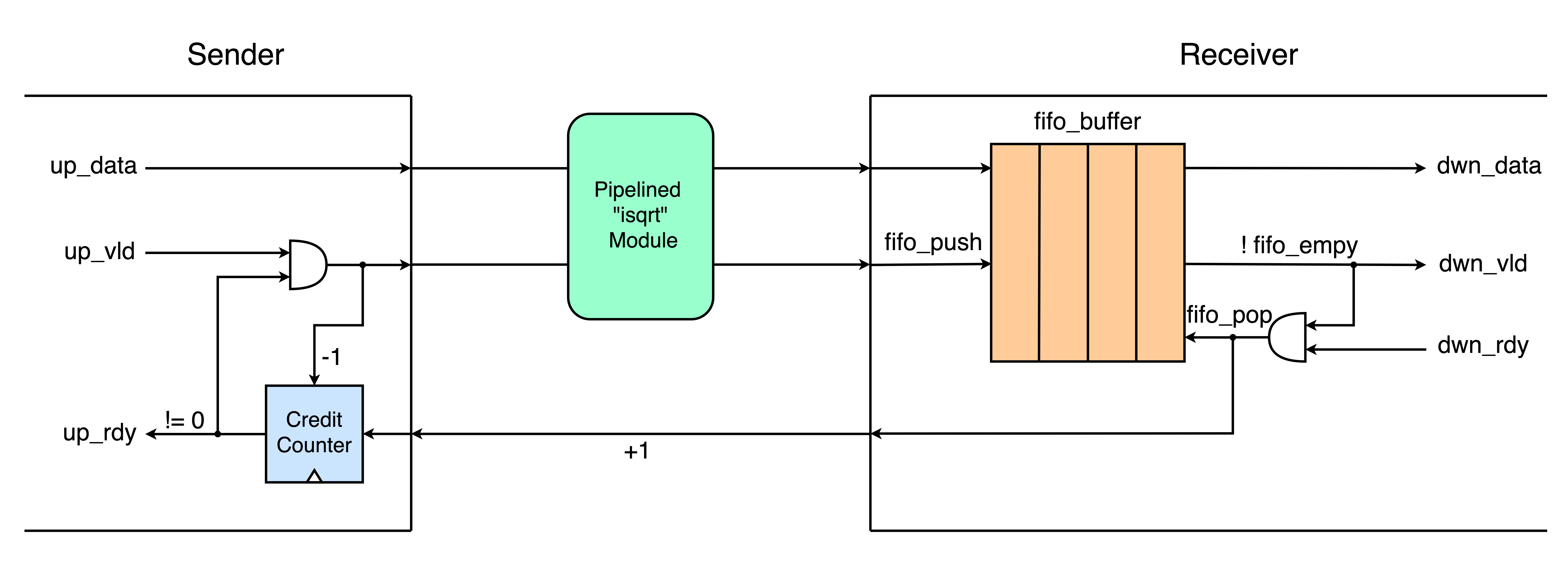
The figure below shows the implemented credit-based flow control with the pipeline module.

A FIFO buffer is implemented at the receiver’s side with the size of the pipeline depth. At the start, the sender is informed of the depth size of the receiver. The “up_vld” is asserted when the data is ready to be transmitted. The “up_rdy” is asserted as long as the credit counter is not zero. The sender transmits the data only when up_vld and up_rdy are set high. The sender does not transmit the data when the credit counter is zero. At the receiver side, the FIFO receivers the transmitted data. The data from the FIFO is valid as long as the FIFO is not empty, indicating that there is data in the FIFO buffer. The “dwn_vld” signal is asserted when the FIFO is not empty. The “dwn_rdy” signal is set high when the receiver is ready to process the data. Data from the FIFO is popped when the FIFO is not empty and when the receiver is ready to process the data. When the receiver pops the data from the FIFO buffer, a credit signal is sent to the sender to increment the credit counter indicating that there is buffer space available for the sender to send more data. If the sender has sent all its credits and has not received new credits yet, it must wait. As soon as it receives new credits, it will resume sending data.
Perks
- Efficient hardware utilization when compared to valid/ready control.
- Performance of the design can be increased with increase buffer size.